
Blog
- 2022-04-13
- 4 min read
Solving the problems of ozonelayer depletion and global warming
To protect the ozone layer, up until the 2010s, we had sought to convert to centrifugal chillers utilizing a fluorocarbon (HFC-134a) that does not contribute to the destruction of the ozone layer, as an alternative to specified fluorocarbons (Ozon-Depleting Substances). Since COP21 in 2015, not only from the viewpoint of protecting the ozone layer but also that of combatting global warming caused by increase of greenhouse gas emissions, regulations on fluorocarbons have intensified globally, and there are now needs to develop products utilizing refrigerants with a lower Global Warming Potential (GWP). To meet these needs and taking care of environment, MHI Thermal Systems has been working on the development of next-generation centrifugal chillers that achieve further reductions in environmental impact together with high-level performance.
Three key factors for MHI Thermal Systems’ advanced centrifugal chillers
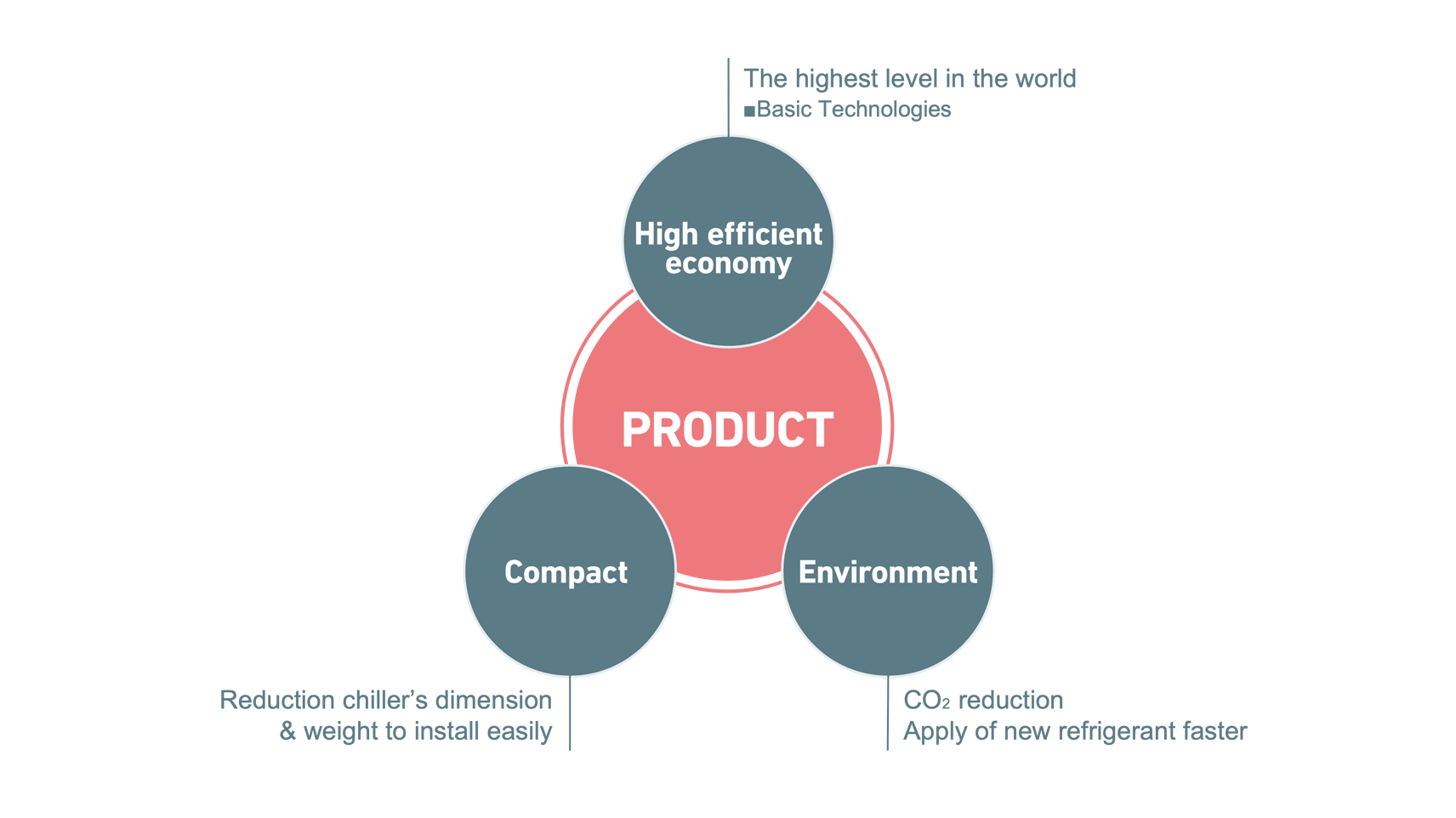
1. Environment
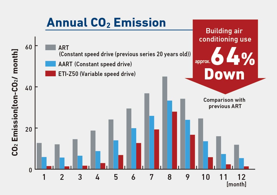
Energy saving solutions and reduction of CO₂ emissions
Comparing with previous models (centrifugal chillers) around 20 years ago, which are currently approaching replacement, MHI Thermal Systems' state-of-the-art centrifugal chillers can reduce power consumption by around 60%, with improvements of system in Balance of Plant (BOP). According to the TEWI (Total Equivalent Warming Impact) index, which considers the greenhouse gas effects of refrigerant leakage in addition to CO₂ emissions from primary energy consumption during operation, MHI Thermal Systems’ centrifugal chillers can achieve almost zero global warming effects due to direct emissions in comparison with previous models. We have also achieved a reduction of around 60% in total equivalent global warming effects (combining the effects of global warming caused by indirect emissions).
2. High efficiency
Conversion to low-GWP refrigerants with maintaining high performance
As for our compressors, we have implemented aerodynamic designs to achieve greater flow rate (increasing capacity) with the same body shapes as our existing series, in response to the increase in specific volume of low-GWP refrigerant. Since compressor efficiency typically decreases when we attempt to increase the size of the flow rate, we applied CFD (Cozmputational Fluid Dynamics) analysis to the flow path inside the compressor to optimize the shape. As a result, we succeeded in increasing compressor intake flow rate by 60% with maintaining compressor efficiency relative to existing models.

As for our heat exchangers, we have adopted thin, lightweight, high-performance heat transfer tubes with high heat-exchange efficiency and strength. CFD analysis has also been used on heat exchangers to optimize numbers of heat transfer tubes, combinations of lengths and diameters, and tube arrangement, minimizing heat transfer area with maintaining performance. In addition, the vapor-liquid separation structure of the evaporator has been reviewed to avoid suction of liquid refrigerant that affect life of the compressor, the uneven phase changes and the localized refrigerant flow velocity increases. The structure of our condensers has also been reviewed, with bias in flow velocity distribution suppressed to enable efficient overall exchange between the refrigerant distributed in the condenser and the heat transfer tubes, avoiding a decrease in the performance of heat exchange due to pressure drop. Our control panels utilize the latest microcomputer circuitry to realize higher-precision control and higher-speed calculations than in previous models. The LCD display unit has been enlarged and a touch panel type display has been adopted to improve operability and visibility for operators. Help information for response procedures in the event of problems can also be displayed on-screen rapidly, and announcements during maintenance periods and automatic communication functionality have been expanded and enhanced to improve convenience for users.

3. Compact
Larger-capacity centrifugal chillers that can be operated in confined spaces
We have been working to develop the advanced centrifugal chillers based on the concept of reducing installation area and weight of the chillers, and have achieved greater compactness by applying the latest technology for blade shapes to compressors, high-speed rotation of motors, and high-performance heat transfer tubes for heat exchangers. As a result, installation areas can be reduced by around 35% in comparison with existing models, and cooling capacity per unit installation area has also been improved. When customers replace old chillers with new ones, existing spaces for old chillers can be utilized for new ones. Not only additional space-saving is possible, but also eliminating a need for moving BOP and change of piping systems would be minimized. As a result of these improvements, it has become easier to carry in and install our centrifugal chillers, which has earned us high appraisal from customers.
DOWNLOADS


Related News
- MHI Thermal Systems Wins 22nd "Environment Minister's Award for Global Warming Prevention Activity" for its High-efficiency Next-generation ETI-Z Series Centrifugal Chillers
- MHI Thermal Systems to Launch New Series of Large-Capacity Centrifugal Chillers Adopting Low-GWP Refrigerant -- Constant-Speed JHT-Y and Inverter-Equipped JHT-YI Will Reach Market in June --
- Tags
- Thermal systems
- Carbon neutral
Mitsubishi Heavy Industries Thermal Systems, as one of the core subsidiaries of Mitsubishi Heavy Industries group, offers thermal technologies and solutions.